Getting the Scoop
Hand-working a custom modification
from Sport Aviation, February 2003
by Kent White
The prototype process calls for the fabrication of either parts or a single aircraft to prove the airworthiness of a new design or to improve some aspect of it. Once the prototype is proven, production fabrication methods are employed, usually with much of the dimensional and assembly information taken from the prototype.
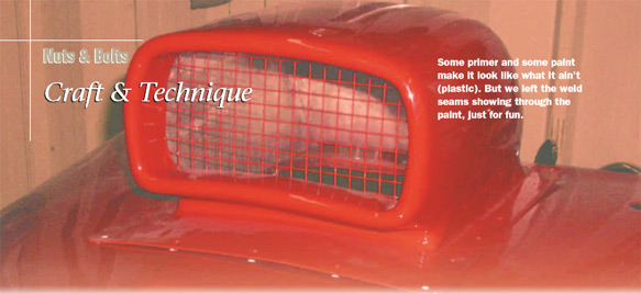
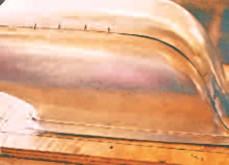
 The finished scoop is hand-formed aluminum, ready for primer, paint, and installation.
This hand-working process also keeps old birds in the air or modifies them. Some old aircraft use an external scoop to feed fresh cold air into the carburetor, increasing horsepower by providing air of greater density. The owner of a custom Stearman wanted such a scoop, and rather than borrowing one from another design that sorta looked okay, we designed and built a custom scoop.
Working from a 3-D pattern is essential, so I begin by cutting white poster board into a rough profile. After a few versions that are too fat, too short, or too long we arrive at one that satisfies both the carb inlet area and complements the look of the existing custom cowling. To simulate the finished product I carefully tape this cardboard piece into place, and sometimes spray paint it to match the cowling, making the appearance as real as possible.
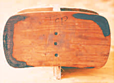 The frontal area was designed first in cardboard and then checked for size and shape by mocking it up on the airplane.
Patterning the scoopâs front view is next, using the same cut-and-snip-and-tape method as on the profile. It, too, is taped in place to fill out the 3-D aspect. Once finished with all the little trimming and taping adjustments, we determine the width of the base flange that will connect the scoop to the cowling, taking into account how much it will take to step over any rivet lines, stiffeners, or brackets already in place. I now tape out this âsafe areaâ for fastening the scoop onto the cowling, and then I make the base flange fit within those confines.
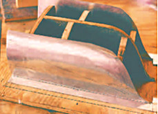
Transferring the cardboard patterns to 1/2-inch plywood, which is cut to match, gives us the start of a hard 3-D mockup or âstation buck.â I fasten these first two pieces to a plywood base using drywall screws. Seeing the wood framework for the first time, I realize that it needs a few more pieces for a more âsolid feelâ and give my metal parts more support and confirmation when fitting them. Interpolating the curves as I go, I make a few âpaper dolls,â transfer them to plywood, and then screw them in place. A flexible ruler checks the contours and a last bit of sanding gives the edges a smooth series of curves.
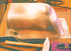
The “master” panel is gently formed to the “buck,” before stretching and shrinking it to final fit.To cover this buck with metal I start by making some panels out of butcher paper. I flow the paper over the contours, imagining where Iâll put the welds and what corners I can get myself into. Breaking a part into bite-sized pieces is a stumbling block to many craftsmen, but I look for pieces that are a handy size to work with. If at all possible, I try to have breaks, joints, or seams on high crowns. Centering the seam on the high crown limits the amount of weld-related distortion and confines it to the immediate vicinity of the weld, rather than letting it infect a large area of carefully worked metal.
Maybe itâs Murphyâs Law, but making a new part is usually a learning experience because you always find a better way to make the second one. After tinkering with the paper, I decide on a four-piece scoop. The main section will be on the top, from front to back, then two sides, and with a little chin section under the intake opening.
After cutting out the paper patterns, I tape them on the sheet metal, allowing for about a 1/2 inch of excess, total. Using a variety of snips and shears to cut out the material, make one long continuous cut by keeping the cutter fully engaged in the material. Otherwise, the cut becomes jagged with âDutch daggersâ created by re engaging the cutter in a series of new directions, segmenting the curves. Deburring the edges (or wearing lightweight Kevlar gloves) will save blood and leave a nicer looking pair of hands at the dinner table.
 The sides are next, with the “chin” being last.
Typical layout tools include the black marker, soft lead pencil, ballpoint pen, and layout dye. With the fluids or dyes, remember that heavy scribing will cause stress risers. These risers can lead to premature part failure when operating stresses and vibration work on that nick, gouge, or cut and grow them into a crack. Take great care to sharpen the scribe or dividers and use only very light pressure when scratching the surface. Use a scribed line only when shearing or cutting; use marking pens for hems, bends, and folds. Mark every detail possible, like âbend up,â âfold down,â âinside,â âright,â and âup.â Even though you may feel foolish being so anal, think how youâll feel after making two LEFTS.
When deciding which piece to form first I always start with the easy ones because I never know if Iâll quit or get fired. Seriously, some parts may have a master piece, one that must precede the others if the others are to have the proper confirmation throughout the assembly and fitting process.
The scoopâs large top center section will work well to locate all the other pieces, and because its shape is autonomous, itâs the âmaster.â Shaping the .050-inch 3003 halfhard aluminum into the center panelâs proper contours requires a little stretching across the main bend, simple radius bends along the sides, and a little shrinking on the sides at the bend. I put the stretch in first, using a shot bag and a mallet. The sides are radiused over a Tstake having a 1-inch diameter using the plastic dead-blow hammer, and the little edge shrinks are done with an auto body dolly and the dead-blow hammer.
 All four pieces are formed and fit, with witness marks keeping them aligned during tack welding.
Trying the panel for fit several times, I mark inconsistencies as I go. I make sure to stretch it a bit more where it hits the buck and shrink it a bit where it lifts too high. With the top finished, I lay out the sides, blanking them large enough to flange their bottom edges and to overlap their top edges. The sides need to curve from top to bottom, with a little edge shrinking at the upper corners and a nice sharp radius at the lower rear to transition onto the back of the scoop.
After the sides meet the top and fit the buck, look at the proposed weld seam. Plan to keep it centered on the scoopâs corner radius. To create a straight trim line, connect points along the center with a flexible ruler and create a line of marker pen dots. Whether the line masters from the top or the side makes no difference, as the goal is simply to have the seam straight and centered on the radius.
After trimming the panel, reinstall it on the buck and scribe off it onto the related part. Cutting the scribe line right on the money makes a butt weld and not a lap weld. Make witness marks at a few points along the way, to ensure correct alignment when you weld. Only when all three parts are fit and trimmed to each other do you think about tack welding them together. Donât mind cooking the buck when tacking the parts in proper alignment; the aroma of pinewood smoke is a small sacrifice for accurate parts. In some cases, I fit against plastic, fiberglass, or plaster and thus avoid tack welding on the buck, but in this caseâitâs time for the barbecue!
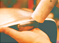 After welding and planishing the entire scoop, the intake is formed to receive a bit of detail.
After welding the sides and gently working the seams true again, refit the assembly and begin to work out the front, or air inlet. Bend a simple U over the ever-handy Tstake thatâs set in against the front of the scoop. Work the lower corners into each area to make the tight little transition we saw earlier at the back. Little details like these make the part look nicer. Tangling around the opening with every small contrivance I can bang the metal with, I finally get the thing formed, fit, snipped, and tacked. I finish working it as I weld, a nifty little process I call working in. (You will see this later, too.)
I prefer gas welding over TIG for this panel working because TIG beads are thick and heavy and the penetration is mediocre without expensive back purge. The oxy acetylene weld beads are faster to make, cheaper, and thinner and flatter, enabling one to easily planish the work smooth. The appearance side is then bumped up and down gently with a dolly to level it up. When all contours are fairly close to confirmation, planishing with a spoon or slapper may commence.
Metal finishing is defined as âsmoothing by removing metalâ and includes grinding, filing, sanding, and polishing. FAA Advisory Circular 43.13-1B, Acceptable Methods and Practices, Chapter 4, Section 5, Paragraph e7 says: âDo not file or grind welds in an effort to create smooth appearance, as such treatment causes a loss of strength.â A light kiss with the file on the high spots of the weld-bead only should allow for good planishing, which will suffice for any paint-grade part, leaving some good primer-surfacer coats to finish up.
 Checking left and right contours with a contour gauge.
An edge return is the last part made, a little detail that finishes the intake. I make it by measuring the openingâs circumference, cutting a 3/4-inch wide strip of aluminum stock, forming it to fit the opening minus the edge radius, and then welding the ends to close the loop. Then the band is radiused at the edge to fit the opening. When installed for the first time, the fit is a littleâ¦surprising. Time to gather up your courage and tap around the face of the opening, closing up the gap, and truing it up in all planes for welding. When it is somewhat close, tacking commences, and at the same time tapping away with the spoon to get the contour just right. When tacking is done, I weld the whole thing from A to Z. A little planishing, a touch with the file, and it is ready for paint!
EAA Technical Counselor Kent White achieved master technicianâs status in 1976 at Harrahâs Auto Collection, where he restored metal components for aircraft and autos. He started his own metal restoration company in 1977 and now teaches, writes, and develops tools for metalworking while he still pounds out parts. He encourages any welder or metalworker, man or woman, to contact him in regard to preserving the traditions of aircraft metalworking.
Contact him.